
Designing a Fire Alarm System Using Arduino, Temperature and Gas Sensor in TinkerCAD
Simulation software is invaluable in the design and testing of electronic circuits and devices, offering a risk-free environment to identify and mitigate potential hazards. In this article, we will design a fire alarm system using TinkerCad, interfacing an Arduino with temperature and gas sensors. This project illustrates how simulation can streamline the creation of effective and safe electronic systems.
Components Required
While physical components are not necessary for TinkerCad simulation, understanding the hardware involved is crucial. Below is a list of components we will simulate:
1. Arduino UNO Board
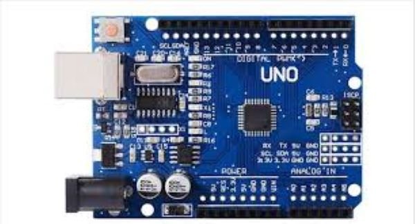
The Arduino UNO is a microcontroller board that receives inputs from connected sensors and provides output actions to devices. It is versatile and commonly used for various sensor integrations.
2. LM-35 Temperature Sensor
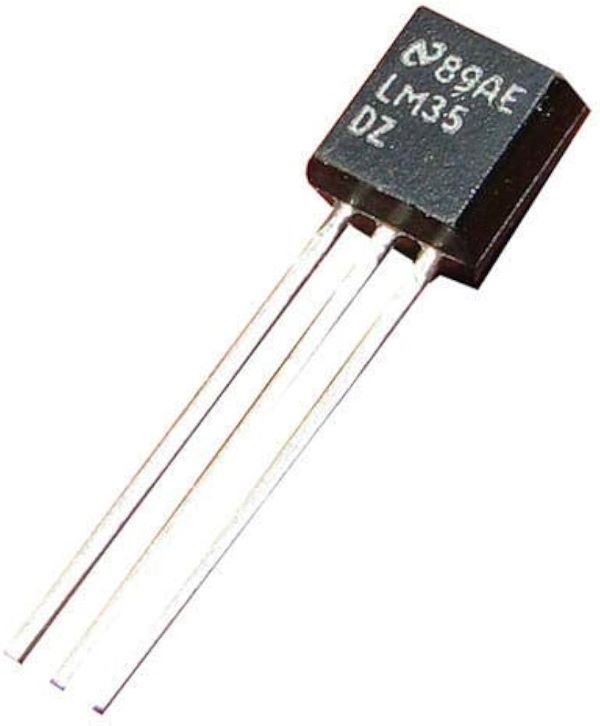
This sensor provides an analog output proportional to the instantaneous temperature, crucial for detecting temperature changes indicative of fire.
3. MQ2 Gas Sensor
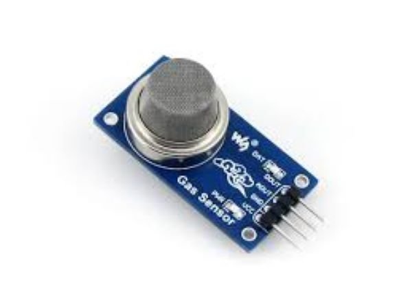
The MQ2 sensor detects gas concentrations or the presence of smoke in the atmosphere, generating a voltage output based on the detected gas levels.
4. Resistors (1k Ohm)
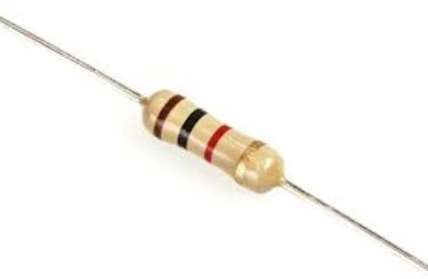
Resistors control current flow and divide voltage within the circuit, protecting sensitive components from damage.
5. Breadboard
A breadboard is used for constructing the circuit. It facilitates the connection of components without soldering, making the design process flexible and straightforward.
6. LED
The Light Emitting Diode (LED) serves as a visual indicator in the alarm system.
7. Piezo Buzzer

The buzzer generates an audible alert when the alarm is triggered, enhancing the system’s effectiveness.
8. Jumper Wires
These wires establish connections between different devices in the circuit.
Note: The description of the electrical components is given for reference. We don’t need the physical components for this project since the circuit simulation is done in the TinkerCad software.
Software Requirement
TinkerCad Circuit Simulation Software
TinkerCad is an online simulation tool used for circuit design. It contains all the electrical components required to build circuits and run them virtually.
Circuit Connections and Working
The following steps outline the connections needed to build the fire alarm system circuit in TinkerCad:
- Power and Ground Connections:
- Connect one line of the breadboard to the ground and the other to the power supply.
- Connect the 5V pin of the Arduino Board to one line of connection pins on the breadboard.
- Connect the ground terminal of the Arduino Board to the other line of the breadboard.
- Temperature Sensor Connections:
- The temperature sensor has three pins: Ground, Vout, and Vs (Supply).
- Connect the Vs pin (4-20V range) to the power supply line of the breadboard.
- Connect the Ground terminal to the ground line of the breadboard.
- Connect the Vout terminal to Analog pin A1 of the Arduino Board.
- Gas Sensor Connections:
- The gas sensor has six pins.
- Connect three pins of the gas sensor directly to the power supply line of the breadboard.
- Connect one of the remaining three pins to Analog pin A0 of the Arduino Board.
- Connect the middle pin to the ground line of the breadboard.
- Connect the third pin to a resistor and then to the ground line.
- Piezo Buzzer Connections:
- Connect the ground pin of the buzzer to the ground line of the breadboard.
- Connect another pin of the buzzer to digital pin 7 of the Arduino Board.
- LED Connections:
- Connect the cathode of the LED to the GND pin of the Arduino.
- Connect the anode of the LED through a resistor to digital pin 13 of the Arduino.
Code
Below is the Arduino code for the fire alarm system. This code reads the input from the temperature and gas sensors and triggers the LED and buzzer if the readings exceed the defined thresholds.
// Define pins
const int tempPin = A1; // LM35 Temperature Sensor connected to A1
const int gasPin = A0; // MQ2 Gas Sensor connected to A0
const int buzzerPin = 7; // Piezo Buzzer connected to digital pin 7
const int ledPin = 13; // LED connected to digital pin 13

// Threshold values
const float tempThreshold = 50.0; // Temperature threshold in degrees Celsius
const int gasThreshold = 300; // Gas sensor threshold value

void setup() {
// Initialize the serial communication
Serial.begin(9600);

// Initialize the pins
pinMode(buzzerPin, OUTPUT);
pinMode(ledPin, OUTPUT);

// Ensure buzzer and LED are off at start
digitalWrite(buzzerPin, LOW);
digitalWrite(ledPin, LOW);
}

void loop() {
// Read temperature value from LM35 sensor
int tempReading = analogRead(tempPin);
// Convert the reading to temperature in Celsius
float temperature = (tempReading / 1024.0) * 5.0 * 100.0;

// Read gas sensor value from MQ2 sensor
int gasReading = analogRead(gasPin);

// Print the sensor values to the Serial Monitor
Serial.print("Temperature: ");
Serial.print(temperature);
Serial.print(" C, Gas: ");
Serial.println(gasReading);

// Check if temperature exceeds threshold or gas sensor detects gas
if (temperature > tempThreshold || gasReading > gasThreshold) {
// Trigger the buzzer and LED
digitalWrite(buzzerPin, HIGH);
digitalWrite(ledPin, HIGH);
} else {
// Turn off the buzzer and LED
digitalWrite(buzzerPin, LOW);
digitalWrite(ledPin, LOW);
}

// Small delay before the next loop
delay(1000);
}
Conclusion
By using TinkerCad for simulation, we can design and test a fire alarm system effectively. This approach allows us to ensure all connections and components function correctly, mitigating potential risks before physical implementation. Simulation tools like TinkerCad are essential in modern electronics design, providing a safe and efficient way to bring innovative ideas to life.