
Boost Converter: Design, Working & Applications
Introduction
In today’s modern world, the boost converter plays an important role in voltage regulation and power delivery across various applications. Its ability to efficiently step up voltage levels from lower inputs to higher outputs has made it essential in industries ranging from renewable energy systems to portable electronics. Generally, the boost converter operates by manipulating the energy storage and release of an inductor. Initially, the input voltage charges the inductor, storing energy in the form of a magnetic field. Upon switching off, the inductor releases this stored energy, inducing a voltage across the output capacitor that surpasses the input voltage, thus “boosting” it.
By adjusting the duty cycle of the switch, the output voltage can be precisely regulated, ensuring stable and efficient power supply to the load. Its simplicity and high efficiency have positioned the boost converter as a fundamental component in electronics. It is used for applications requiring higher voltages, such as battery-powered devices, and for grid-tied inverters in renewable energy systems. Let’s explore what a boost converter is and how it works in detail.
What is Boost Converter?
A boost converter is also known as a step-up converter. It is a type of DC-DC converter that increases the input voltage to a higher output voltage. Generally, It is used to including power supplies, battery chargers, and renewable energy systems. The boost converter consists of several key components like, an inductor, a diode, a capacitor, and a switch (usually a transistor). These components work together to regulate the voltage and provide a stable output.
As you can see in the below diagram, the boost converter consists of several key components that work together to achieve the desired voltage conversion. The DC input voltage is the initial voltage that needs to be boosted, obtainable from a battery, a power supply or any other DC source.
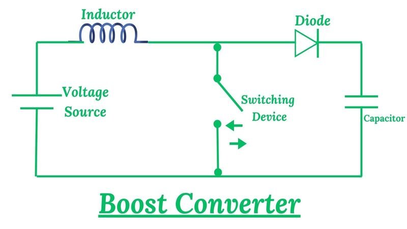
The switch is typically a semiconductor device such as a MOSFET or a BJT, which controls the flow of current through the circuit, alternating between on and off states to regulate energy transfer. The inductor is a passive component that stores energy in its magnetic field and is connected in series with the switch and the load. The diode permits current flow in only one direction and is connected in parallel with the switch and the inductor. Capacitors are used to store energy in their electric field and are connected in parallel with the load. Finally, the load is the device or circuit that requires the boosted voltage for its operation.
Working Principles of Boost Converter
The working principles of a boost converter involve the efficient transformation of input voltage to a higher output voltage. It operates through the interaction of key components such as an input voltage source, an inductor, a switch (often a transistor), a diode, and an output capacitor. Understanding its operation typically involves two primary modes: Mode I and Mode II:
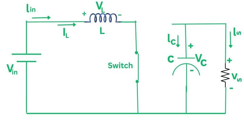
Mode I : Switch is On, Diode is OFF
During this mode, the switch is on and allows current to flow from the input source to the inductor. The inductor stores energy in the form of a magnetic field. As the current increases, the energy stored in the inductor also increases. The diode remains reverse-biased and in the OFF state, preventing any current flow through it and acting as an open circuit. Mode I primarily focuses on storing energy in the inductor. The duration of Mode I depends on various design parameters of the boost converter, including the inductance value, input voltage, and desired output voltage.
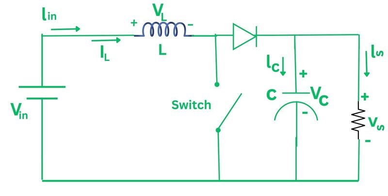
Mode II : Switch is OFF, Diode is ON
When the switch is turned off, Mode II begins. In this mode, the diode connected across the inductor becomes forward biased. This allows the inductor to discharge its stored energy into the load. The diode acts as a closed switch, enabling the current to flow in a loop through the inductor, diode, and load. Mode II is important for maintaining a continuous flow of current and energy transfer in the circuit, which ensures that the output voltage remains higher than the input voltage. Boost converters rely on Mode II to step up the input voltage to a higher level by allowing the inductor to discharge its stored energy into the load.
Applications of Boost Converter
The boost converter is a popular power electronics circuit that is widely used in various applications. Here are some common applications of boost converter:
- Renewable Energy Sources: The boost converter is in renewable energy systems, such as solar and wind power systems. In these systems, the energy generated from solar panels or wind turbines is typically at a low voltage level. The boost converter is used to step up this low voltage to a higher level, which can then be fed into the grid or used to charge batteries.
- Electric Vehicles: EVs rely on high-voltage battery packs to power the electric motor. However, the voltage level of the battery pack is not always suitable for driving the motor directly. The boost converter is used to step up the battery voltage to a level that can efficiently drive the motor. Additionally, the boost converter is also used in the charging infrastructure of EVs to convert the grid voltage to the appropriate level for charging the battery.
- LED Lighting: LEDs require a specific voltage level to operate efficiently. The boost converter is used to step up the voltage from a low input voltage, such as a battery or a low-voltage power supply, to the required level for driving the LEDs. This allows for efficient and reliable operation of LED lighting systems, which are becoming increasingly popular due to their energy-saving benefits.
- Telecommunications: In the field of telecommunications, the boost converter is used in various applications. For example, it is used in power amplifiers to increase the voltage level of the input signal. This helps in boosting the signal strength and improving the overall performance of the communication system.
- Portable Electronic device: The boost converter is commonly found in portable electronic devices, such as smartphones, tablets, and laptops. These devices often operate on battery power, which is typically at a lower voltage level. The boost converter is used to step up the battery voltage to the required level for powering the device’s components, such as the display, processor, and memory. This enables the devices to operate efficiently and deliver the desired performance.
Advantages and Disadvantages of Boost Converter
Here, we discuss the advantages and disadvantages of boost converter which helps you to understand their capabilities and limitation:
Advantages of Boost Converter
Here are some advantages of boost converter:
- Efficient voltage boosting: Boost converters are efficient at stepping up input voltage to a higher output voltage level. They can achieve high efficiency levels, especially when designed and operated within their optimal operating conditions.
- Compact size: Boost converters can be designed to be relatively small and lightweight compared to other voltage conversion topologies. This makes them suitable for applications where space is limited, such as portable electronic devices and embedded systems.
- Lower ripple voltage: Boost converters typically produce output voltages with lower ripple compared to some other types of voltage converters. This can be advantageous in applications where a stable output voltage is use for proper device operation.
- Higher output power capability: Boost converters can handle relatively high output power levels, making them suitable for applications requiring moderate to high levels of power delivery.
- Wide input voltage range: Boost converters can often accommodate a wide range of input voltages. This flexibility allows them to be used in various power supply applications where the input voltage may vary significantly.
- Good for battery-powered applications: Boost converters are commonly used in battery-powered devices to efficiently step up the lower voltage provided by batteries to levels required by the load. This extends the usable lifetime of the battery and maximizes the device’s operational time.
Disadvantages of Boost Converter
Here are some disadvantages of boost converter:
- Higher electromagnetic interference (EMI): Boost converters can generate higher levels of electromagnetic interference (EMI) due to the rapid switching of currents. This can potentially cause interference with nearby electronic devices and may require additional filtering or shielding measures.
- Requires high-side switch: Boost converters require a high-side switch, which adds complexity to the circuit design. High-side switching can also introduce additional challenges related to gate drive circuitry and voltage isolation.
- Higher voltage stress on components: Boost converters subject components such as the inductor, diode, and capacitor to higher voltage stresses compared to other converter topologies. This may necessitate the use of components with higher voltage ratings, increasing cost and complexity.
- Complexity in design and control: The design and control of boost converters can be relatively complex compared to simpler voltage conversion topologies. They often require precise control systems, including understanding bode plots in control systems, to achieve desired performance characteristics.
- Non-isolated (unless coupled with other circuitry): Basic boost converters are non-isolated, meaning there is no electrical isolation between the input and output. This can be a limitation in applications requiring isolation for safety or noise immunity reasons, although isolated versions can be implemented with additional circuitry.
- Limited output current capability: While boost converters can handle moderate to high output power levels, they may have limitations in terms of maximum output current capability. This limitation can be a factor in applications requiring high current output, such as motor drives or high-power LEDs.
FAQs Related to Boost Converter
Here are some FAQs Related to Boost Converter:
What is another name for a boost converter?
Another term for a boost converter is a step-up converter. This type of converter increases the input voltage to a higher output voltage level. It achieves this through a switching operation, where energy is stored in an inductor during the switch-on period and then released to the output during the switch-off period.
Why MOSFET is used in boost converter?
MOSFETs are used in boost converters due to their ability to efficiently switch high currents. As a component in the converter’s switching circuit, MOSFETs facilitate the rapid on/off switching required for voltage boosting. This enables the conversion of input voltage to a higher output voltage, a key function of boost converters.
What are components of boost converter?
A boost converter consists of a MOSFET for switching, an inductor for energy storage, a diode for current flow and a capacitor for voltage smoothing. Control circuitry regulates the MOSFET’s duty cycle to achieve the desired output voltage.
Is a boost converter AC or DC?
A boost converter is a type of DC-to-DC converter, meaning it operates with direct current (DC) input and output. It increases the input voltage to a higher output voltage level, making it suitable for applications requiring voltage boosting. The input power source can be either AC or DC, but the output of the boost converter is always DC.